Scene 1 (0s)
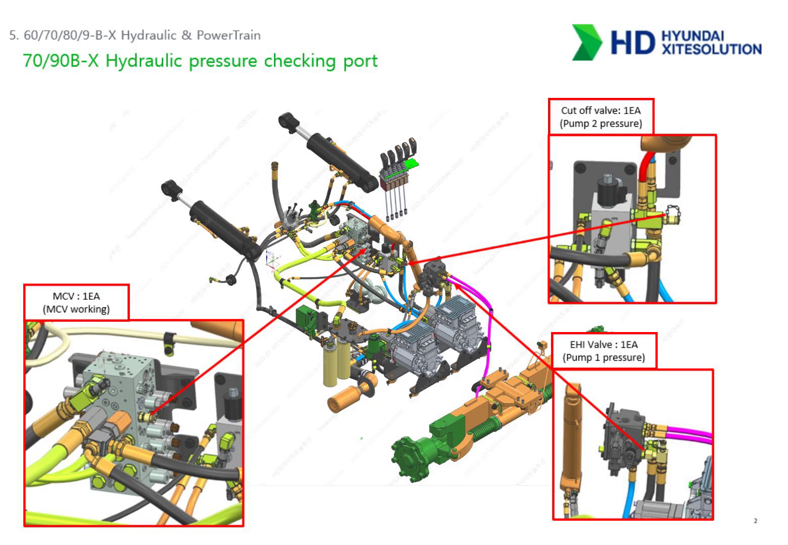
[Audio] This slide covers the three hydraulic pressure measurement ports on the 8-ton model and how to use them for diagnosis. The MCV port is located on the front face of the main control valve block, similar to the 5-ton position. This port measures the main working pressure for lift, tilt, and attachment functions. The target reading depends on the model: 210 bar for standard 60, 70, and 80B-X models, and 250 bar for the 90B-X and 80B-XL. Do not apply the 5-ton reference of 215 bar to 8-ton machines. The EHI valve port is on the EHI valve block on the left side of the machine. This port measures pump 1 output pressure and steering circuit pressure simultaneously. When the steering wheel is turned to full lock, the reading should reach 170 bar — the EHI relief setting. This is significantly higher than the 5-ton's 135 bar. Make sure technicians are using the correct reference value. The cut-off valve port is on the cut-off valve block on the right side of the machine. This port measures pump 2 output pressure and accumulator charging pressure. The reading should cycle between 100 bar on the low side — cut-in — and 140 bar on the high side — cut-out. If the accumulator pressure is not holding in this range, or if pump 2 is not building pressure correctly, this is where to start the diagnosis..
Scene 2 (1m 40s)
[Audio] This slide covers the electronic joystick control system on the 8-ton model and the MCV port configuration. The most visible change compared to older engine forklifts is what connects the joystick to the MCV. On an IC forklift, a bundle of hydraulic pilot hoses ran from the joystick down to the valve. On the 8-ton B-X, those hoses are completely replaced by an electrical wiring harness. When the operator moves the joystick, an electronic signal is generated and sent through the wiring to the solenoid valves on the MCV, which then direct hydraulic flow. This eliminates all hydraulic leak risk inside the cab and allows significantly more precise proportional control. For the MCV port layout: the P port is the inlet — combined flow from pump 1 through the EHI valve and pump 2 through the cut-off valve enters here. The T port is the return line back to the hydraulic tank. Port A1 handles lift and lowering. Ports A2 and B2 handle tilt in and out. Ports A3 through A5 and B3 through B5 are the auxiliary ports for side shift, fork positioner, and other attachments. For service: when a specific function is slow or absent, identify which port handles that function and measure pressure at the MCV port while operating the function to full travel. This confirms whether the issue is with pressure supply or with the MCV spool for that function..
Scene 3 (3m 14s)
[Audio] This slide covers the MCV pressure settings and valve locations for the 8-ton model. For the first relief valve — main system pressure: the standard 80B-X is set at 210 bar. The 80B-XL and 90B-X heavy-lift variants are set at 250 bar. When a lift force complaint is received, always confirm which specific model variant you are working on before making any pressure adjustment. Using the wrong target value will result in either under-pressure or a dangerous over-pressure condition. For the second relief valve — auxiliary attachment pressure: the base setting is 140 bar with the ability to adjust up to 170 bar for heavy attachment applications. This flexibility allows the system to be optimized for the specific attachments used at each customer site. For valve locations on the 8-ton MCV: the manual lowering screw is at the top — the same 1.5-turn limit applies as on the 5-ton. The lowering speed adjustment valve is in the center section. The pressure gauge port is at the bottom, which actually improves accessibility compared to the 5-ton layout. The tilt lock valve is shown on the right-side diagram. When performing MCV service on the 8-ton, photograph the valve locations before disassembly — the layout differs from the 5-ton and confusion between them is a common source of reassembly errors..
Scene 4 (4m 52s)
[Audio] This slide covers relief valve adjustment and manual lowering procedures for the 8-ton MCV. For pressure adjustment: the procedure is identical to the 5-ton. First loosen the lock nut slightly. Then use a hex wrench to turn the adjustment screw — clockwise increases pressure, counterclockwise decreases it. Always monitor the pressure gauge in real time and make changes in small increments. Tighten the lock nut fully after adjustment to prevent pressure drift from vibration. If the screw is loosened too far, it can be ejected from the valve body — never adjust without watching the gauge. Because the 8-ton handles larger flow volumes, pressure changes in response to adjustment are more pronounced than on the 5-ton. Adjust more carefully and in smaller steps. For manual lowering in an emergency: use a 3-millimeter hex wrench and turn the manual lowering screw counterclockwise slowly. The absolute limit is 1.5 turns. This limit is the same on the 8-ton as on the 5-ton — the larger machine size does not change this number. If the mast does not come down after 1.5 turns, the problem is mechanical — the mast may be caught or the cylinder may be seized. Forcing the screw further will eject the valve body and cause uncontrolled fork drop. Stop immediately and identify the mechanical cause. After manual lowering is complete, tighten the screw back to its original position. The tightening torque must not exceed 0.25 kilogram-force meters. Over-tightening will damage the valve seat and cause leakage during normal operation..
Scene 5 (6m 51s)
[Audio] The 8-ton MCV uses the same monoblock one-body structure policy as the 5-ton model. Individual sections cannot be replaced separately — if the internal housing is damaged, the entire MCV assembly must be replaced. However, external connection components shown in the parts diagram — including connectors, elbows, and O-rings numbered 3 through 9 — can be ordered and replaced individually. When a leak appears at a port fitting or connector on the MCV, order the specific external component rather than replacing the full assembly..
Scene 6 (7m 31s)
[Audio] This slide covers the electronic joystick used on the 8-ton model and the critical assembly orientation requirement. The joystick on the 8-ton is designed to look and feel like the hydraulic RCV lever used on IC engine forklifts — the same housing shape and operating movement. However, internally it is a fully electronic device. There are no hydraulic hoses connected to the joystick body, only an electrical connector. Make absolutely certain your technicians understand this distinction — the joystick must never have hydraulic hoses connected to it. The most safety-critical aspect of this joystick is the front mark on the lower body. When installing or replacing the joystick, the front mark must face the mast direction — toward the front of the machine. This is non-negotiable. The joystick uses a two-dimensional Hall sensor to detect both forward-backward and left-right movements. If the joystick is installed rotated 90 degrees from the correct position, the sensor's coordinate axes are also rotated. When the operator pushes the lever forward expecting lift, the sensor reads that as a left-right input and commands tilt instead. This is a dangerous misoperation that can cause serious accidents. Always confirm the front mark orientation before completing any joystick installation. After installation, also confirm the wiring harness is routed without sharp bends or pinch points. A damaged wiring harness will cause intermittent signal faults that are very difficult to trace..
Scene 7 (9m 11s)
[Audio] This slide covers the internal gear pump used on the 8-ton model — a different pump type from the helical external gear pump used on the 5-ton. The 8-ton uses an internal gear pump design with a key feature called gap compensation. The pump automatically compensates for axial and radial clearances as the internal components wear, maintaining high volumetric efficiency even under high pressure. This results in pressure pulsation of approximately 2 percent — extremely low — which means minimal noise and excellent service life under heavy-duty cycling. The 8-ton has two of these pumps. Pump 1 supplies the steering system and MCV. Pump 2 supplies the brake system and MCV. The physical separation of steering and braking into independent pump circuits is a core safety design — even under maximum hydraulic demand from work functions, both steering and braking always have dedicated power. Pump capacity is 40 cubic centimeters per revolution, and maximum operating pressure is 250 bar. For fault diagnosis: the separation of functions makes diagnosis more direct. If steering is heavy but lift is normal, check the pump 1 circuit. If braking response is abnormal but lift is normal, check the pump 2 circuit. If both lift speed and steering are slow simultaneously, both pumps may be affected — check the common power supply and inverter communication for both..
Scene 8 (10m 48s)
[Audio] This slide covers the pump motor RPM control logic for the 8-ton dual pump system and how each pump responds to different operating conditions. In standby — when high voltage is on but no function is being operated — both pumps rotate at a minimum of 50 RPM to maintain readiness. For steering, pump 1 responds proportionally to how fast the operator turns the steering wheel. The faster the wheel is turned, the higher the motor RPM. For the 70B-X model, turning the wheel at 120 RPM produces a motor speed of 486 RPM. For the heavier 90B-X, the same wheel input produces 608 RPM — more flow is required to steer the larger machine. For braking, pump 2 logic is driven by accumulator pressure rather than operator input. When accumulator pressure is between 110 and 140 bar — the charged range — pump 2 stays at 50 RPM standby. When pressure drops below 110 bar, the system detects a safety risk and raises pump 2 to 200 to 250 RPM to recharge the accumulator. When starting from a fully discharged state, pump 2 immediately spins at 400 to 450 RPM to restore brake pressure as quickly as possible before allowing travel. For work functions, when lift or tilt levers are operated, both pumps 1 and 2 increase RPM together to deliver combined maximum flow to the MCV. This combined output is what gives the 8-ton its heavy-lift capability. For diagnostic monitoring: if the machine behaves abnormally, use the diagnostic tool to check whether each pump's actual RPM matches the expected value for the current operating condition. A pump running at the wrong speed — too low or not responding at all — indicates either a controller fault or a communication issue between the VCU and the pump inverter..
Scene 9 (12m 57s)
[Audio] This slide compares the conventional hydraulic steering system on the engine forklift to the electronic steering system on the 8-ton B-X series. On the conventional engine model, the steering wheel mechanically drove an Orbitrol hydraulic unit that directly pushed oil to the steering cylinder. The system was reliable but required heavy hydraulic piping into the cab and produced steering feel that varied with system pressure. On the 8-ton B-X, the steering wheel is connected to a non-contact Hall sensor that generates only an electronic signal — no hydraulic connection at the wheel. This is called steer-by-wire. The electronic signal goes to the Rexroth RC controller, which sends commands through CAN J1939 communication to the Danfoss EHI valve. The EHI valve then controls hydraulic flow to the steering cylinder with precision that is not possible with a mechanical system. A non-contact Hall sensor on the rear axle measures the actual wheel angle and sends continuous feedback to the controller. The controller compares the commanded angle to the actual angle and adjusts the EHI valve output to close the gap. This closed-loop feedback is what makes the 8-ton steering so precise. The elimination of hydraulic piping into the cab removes multiple potential leak points and simplifies the steering circuit significantly. Variable pump RPM control means the pump only runs as fast as the current steering demand requires — energy is not wasted maintaining unnecessary flow. For service: when steering problems occur on the 8-ton, the diagnostic approach changes from the 5-ton. Check the CAN communication to the EHI valve and the Hall sensor voltage at the steering axle before opening any hydraulic component. The steering system is primarily an electronic control problem, not a mechanical hydraulic problem..
Scene 10 (14m 57s)
[Audio] This slide shows the complete hardware layout of the 8-ton steering system and how each component connects in the signal and power flow. The E-steering wheel and column contain the Hall sensor that generates the electronic steering command. The sensor detects rotation direction and speed with no mechanical contact — high durability in the forklift environment. The steering column no longer has hydraulic hoses running through it to the cab. The EHI valve in the center of the diagram receives the electronic signal from the steering column sensor and converts it into proportional hydraulic flow. This is the component that makes the 8-ton steering fully electronic. It communicates with the RC controller through CAN and contains internal solenoids and a priority valve that always ensures steering receives oil before work functions. Pump 1 and its motor provide dedicated hydraulic power exclusively for the steering circuit. Because steering has its own pump, it is never starved of flow even when lift and tilt are operating at full speed simultaneously. The steering axle and cylinder at the rear of the machine physically turn the rear wheels based on the oil delivered by the EHI valve. A Hall sensor mounted at the steering axle measures the actual wheel deflection angle and feeds this back to the RC controller in real time. This is the feedback sensor for the closed-loop steering system. For service: if the steering wheel turns but the rear wheels do not respond, check the feedback Hall sensor at the steering axle first. The sensor is non-contact so it does not wear, but physical impact during axle service or contamination can cause failure. The sensor connector is also a common issue — confirm it is fully seated after any axle work..
Scene 11 (16m 50s)
[Audio] This slide explains the four-stage operating sequence of the 8-ton electronic steering system. Stage 1 is command input. When the operator turns the steering wheel, the E-steering Hall sensor detects the rotation direction and speed and generates an electronic signal. No oil is moved at this stage — only data is sent to the controller. Stage 2 is oil supply. The controller receives the signal and commands pump 1 to increase RPM. Oil flows from the hydraulic tank through the pump to the EHI valve. Because pump 1 is dedicated to steering, this supply is independent of any work function demand. Stage 3 is flow distribution. Inside the EHI valve, the controller moves the main spool by a precise amount corresponding to the steering command. The correct volume of oil is directed to the steering cylinder — left or right depending on the wheel direction. Remaining oil not needed for steering returns to the MCV for work functions. This load sensing distribution ensures no energy is wasted. Stage 4 is feedback monitoring. The Hall sensor at the rear steering axle continuously measures the actual wheel angle and reports back to the controller. If the commanded angle and the actual angle do not match within the allowable tolerance, the controller generates an error code and switches to safety mode. For diagnosis: if an error code appears during steering, first check whether all four stages are functioning. Stage 1 — is the steering column sensor producing a signal? Stage 2 — is the pump running? Stage 3 — is the EHI valve receiving the command and responding? Stage 4 — is the axle feedback sensor reporting the correct angle? The diagnostic tool can monitor all four simultaneously..
Scene 12 (18m 52s)
[Audio] This slide covers the detailed specifications of the E-steering Hall sensor on the 8-ton model. The sensor uses a non-contact Hall effect integrated circuit — no internal moving parts make contact with each other. This gives it virtually unlimited mechanical service life in high-vibration forklift environments. It reads absolute position, meaning the current steering wheel angle is known immediately at power-on without needing a homing sequence. Communication is through CAN bus at 250 kilohertz using CAN 2.0B protocol — the same CAN 3 network covered earlier. The signal is digital and encoded, making it highly resistant to electromagnetic noise from the inverter systems. Operating voltage supports both 12 and 24-volt systems — the actual range is 9 to 36 volts, so it is tolerant of battery voltage variation. The connector uses an Amphenol or Deutsch DT04-4P type, which is rated for the vibration and environmental conditions of heavy equipment. For the four-pin wiring: pin 1 — white — is CAN high. Pin 2 — blue — is CAN low. Pins 1 and 2 together carry the steering angle data. Pin 3 — red — is positive power supply. Pin 4 — black — is negative ground. When diagnosing a steering signal fault, start by confirming 12 volts is present at pins 3 and 4. If power is correct but no CAN signal appears, the sensor itself or the CAN 3 wiring is the fault..
Scene 13 (20m 36s)
[Audio] This slide covers the EHI valve port configuration and the electronic control components on the 8-ton steering system. Looking at the port layout: the P port receives high-pressure oil from pump 1. The S-cylinder RH and LH ports connect to the right and left sides of the steering cylinder respectively — if the wheels are not turning, check the hose connections at these ports first. The CF port returns oil not used for steering to the MCV for work functions. The T port at the lower section returns oil to the hydraulic tank. The controller mounted on the left side of the valve body communicates with the VCU and adjusts the internal spool with high precision. The solenoid valve visible on the side is the on-off safety solenoid for the steering system. For the solenoid connector: it uses a 2-pin Deutsch connector with 12-volt DC supply. The signal at pin 2 — PVE pin 6 — must be active for steering to operate. When steering is completely non-functional, measure voltage at this connector first before opening any hydraulic component. If 12 volts is present but steering does not work, the solenoid valve itself may be stuck. If voltage is absent, trace the circuit back to the controller output..
Scene 14 (22m 0s)
[Audio] This slide covers the internal circuit structure of the EHI valve and explains how each component contributes to precision steering control. Components 5 and 6 — the PVE control unit and LVDT sensor — are the precision control core. The PVE unit sends the command to move the main spool. The LVDT sensor measures exactly how far the spool has moved and feeds this back to the PVE unit. This internal electronic feedback loop is what gives the 8-ton its exceptional steering precision even under heavy load — the spool position is constantly verified and corrected. Components 2 and 3 — the solenoid and cut-off valve — are the safety devices. During normal operation they allow oil to flow to the steering cylinder. If an abnormal condition is detected by the controller, these components cut off oil flow immediately, preventing uncontrolled steering movement. This is an active safety protection that does not exist on mechanical steering systems. Components 11 and 12 — the priority valve spool and spring — ensure steering always receives oil before any work function, even when the EHI system is controlling distribution electronically. Component 9 — the pilot reduction valve — maintains internal control pressure at a stable 13 bar. This lower, regulated pressure is what the solenoid bridge uses to move the main spool precisely. Without stable pilot pressure, the spool cannot be controlled accurately. Component 18 — the shock valves on the cylinder lines — protect the EHI body and cylinders from pressure spikes when the rear wheels hit an obstacle at speed. For diagnosis: if steering is completely absent, check whether the solenoid at component 2 is receiving power and whether 13 bar pilot pressure is present at component 9. If steering is intermittent or jerky, check the LVDT sensor signal at component 6 for noise or dropout using the diagnostic tool. If lift works but steering has no force, the priority spool at component 11 may be stuck from contamination..
Scene 15 (24m 18s)
[Audio] This slide shows how the EHI valve hydraulic circuit behaves when the steering wheel is in the neutral position. When power is first applied and the steering wheel is at neutral, the priority valve spring — component 12 — pushes the spool to the left. In this initial position, the EF port to work functions is closed and the path toward the EHI direction valve — component 4 — is open. This ensures steering has first access to oil at startup. Once running with the steering wheel at neutral, the pressure in the CF steering line rises due to the spring force. This shifts the priority valve spool to the right, opening the EF port. Now all pump flow goes to the MCV for work functions, because no steering demand exists. This is the correct and efficient behavior — all available hydraulic energy goes to lifting and tilting when the operator is not steering. The safety cut-off logic at neutral is also important. When solenoid component 2 is not energized, cut-off valve component 3 physically blocks the CL and CR lines going to the steering cylinder. It also cuts pilot pressure to the solenoid bridge — component 7. This means in a neutral state, no external force or electrical glitch can accidentally cause the wheels to turn. For an 8-ton machine, this level of passive safety is essential. For diagnosis: if steering response is delayed by one beat when the wheel is first turned, check the priority spool — component 11. If contamination has made the spool sluggish, it will be slow to shift from the EF position back to the CF steering position. If the rear wheels drift slightly while the steering wheel is at neutral, the cut-off valve seat — component 3 — may be damaged, allowing internal leakage into the cylinder lines..
Scene 16 (26m 20s)
[Audio] This slide explains the activation logic that allows steering to begin when the operator turns the steering wheel. The sequence starts with the PVED-CLS controller — component 5. When the operator turns the steering wheel, the MMI signal — man machine interface data from the steering column sensor — reaches the controller. The controller evaluates the signal and sends 12-volt power to solenoid valve component 2. This electrical enable signal is the prerequisite for any hydraulic steering action — without it, no oil can reach the steering cylinder. When solenoid 2 is energized, cut-off valve component 3 changes position, opening the path for pilot pressure. The pilot pressure generated by reduction valve component 9 — at 13 bar — now flows through to the controller section, putting the system in a ready state to move the main spool. The most important diagnostic point from this slide: if the hydraulic pressure is confirmed correct but the steering wheel does nothing, the fault is in the electronic enable signal, not in the hydraulic circuit. Check whether the PVED-CLS controller is receiving the MMI steering signal from the column sensor, and check whether the controller is outputting 12 volts to solenoid component 2. These are the first two measurements for any 8-ton steering fault. If solenoid 2 has power but steering still does not work, check whether cut-off valve component 3 is operating correctly — it may be mechanically stuck. Then check pilot pressure at component 9 — if pilot pressure is absent or below 13 bar, the main spool cannot be moved regardless of the electronic signal..
Scene 17 (28m 11s)
[Audio] This slide explains stage 3 — actual steering operation — and stage 4 — the safety monitoring system — of the EHI steering circuit. For stage 3, right turn steering: when the operator turns the wheel right, the electrical signal reaches the PVE connector at component 5. The solenoid bridge — component 7 — activates and pushes the main spool — component 4 — to the right. As the spool moves, the LS load sensing circuit inside the spool detects the current steering pressure demand and sends this signal to the priority valve — component 11. The priority valve responds by directing exactly the right amount of oil from pump 1 to meet the demand. This load sensing feedback loop ensures smooth, proportional steering with no wasted energy, even under 8-ton loads. For stage 4, closed-loop safety monitoring: the CLS — Closed Loop Steering — system continuously monitors the main spool position while steering is active. If any unintended movement is detected — movement that does not correspond to the operator's steering input — the controller immediately cuts power to solenoid valve component 2. This causes the pilot pressure from component 9 to dump to tank, and cut-off valve component 3 closes, physically blocking all oil paths to the steering cylinder. The wheels are locked in their current position. This monitoring system prevents the most dangerous possible failure on a heavy forklift — the wheels turning by themselves. It cannot be defeated by a single electrical fault. For service: after any replacement of steering system components, calibration of the steering sensors is required before returning the machine to service. Without calibration, the CLS system may generate false unintended-movement errors and shut down steering unexpectedly during operation..
Scene 18 (30m 21s)
[Audio] This slide covers the 8-ton brake system layout — an independent hydraulic system with dedicated pump, dual accumulators, and SAHR parking brake. The key design principles are independence and stored energy. The brake system on the 8-ton operates completely independently from the work hydraulics. Pump 2 and its controller are dedicated exclusively to braking and steering — no work function demand can affect brake pressure. The two accumulators store pressurized oil so that braking is always available even when the pump is not running. In an emergency where power is lost, the stored pressure in the accumulators provides multiple full brake applications before pressure is exhausted. The parking brake uses SAHR design — Spring Applied, Hydraulic Released. A powerful spring permanently holds the parking brake engaged. Hydraulic pressure from the accumulator is required to push against the spring and release the parking brake. If hydraulic pressure is lost for any reason — hose rupture, electrical failure, power loss — the spring immediately re-engages the brake. This is a fail-safe design: loss of any single system component causes the machine to stop rather than continuing uncontrolled. The cut-off valve monitors accumulator pressure in real time and controls pump 2 operation accordingly. The brake sensor measures pedal application pressure and allows the VCU to blend regenerative motor braking with hydraulic braking smoothly. For service: if pump 2 continues running after shutdown, the accumulator has likely lost its nitrogen pre-charge pressure. If the parking brake does not release after the switch is operated, check whether hydraulic pressure is reaching the parking release port — PA port — at the cut-off valve. If pressure is absent, the parking solenoid valve is the suspect..
Scene 19 (32m 23s)
[Audio] This slide shows the complete brake hydraulic circuit for the 8-ton model, tracing each line from generation to delivery. The supply line begins at the pump and motor at the lower left of the diagram. Oil enters the cut-off valve block at the P port at the bottom. The accumulator charging line passes through the priority valve inside the cut-off valve block and exits through the ACC port. Oil fills the two accumulators at the upper left. The CP1 pressure sensor monitors this charging pressure continuously. Once the accumulators are charged, this pressure also supplies the brake valve P port and the parking solenoid valve, keeping both in a ready state. The service brake line activates when the operator presses the brake pedal. The brake valve opens and oil from the accumulators flows out through the BR port to the brake cylinders at the front drive axle. The pressure delivered to the brakes is regulated to 70 to 80 bar by the brake valve — enough to stop the machine without locking the wheels. The parking brake release line activates when the parking switch is released. The solenoid valve at the top of the cut-off valve block opens, and accumulated pressure flows out through the PA port to the parking brake release port on the front axle. This hydraulic pressure overcomes the SAHR spring and releases the parking brake. The CP3 pressure sensor confirms that release pressure has reached the parking brake and signals the cluster to extinguish the parking indicator. For diagnosis: if braking is weak, measure pressure at the BR port — target is 70 to 80 bar. If parking does not release, measure pressure at the PA port. No pressure at PA with the parking solenoid commanded open means the solenoid valve has failed..
Scene 20 (34m 9s)
[Audio] This slide covers the cut-off valve block — the central control component for the 8-ton brake and accumulator system — and identifies each port and internal valve by physical location. The port locations on the actual block: the P port on the right side receives pump 2 supply. The ACC port on the lower front face connects to the accumulators. The BK port on the upper side face feeds the brake valve — this is the always-pressurized line that keeps the brake valve ready. The PA port on the upper front face is the parking brake release outlet — oil exits here when the parking solenoid opens. The MCV port carries excess flow to the work function circuit after brake demands are met. Internal components and their functions: the parking solenoid at the top — the black assembly — controls whether accumulator pressure reaches the PA parking release port. Check power to this solenoid first when parking will not release. The priority valve — EC1 — determines whether incoming pump flow goes to the accumulator or to the MCV — accumulator charging always takes priority. The proportional relief valve — TS1 — cuts charging off when the accumulator reaches the cut-out pressure and resumes when it drops to cut-in. The check valve — CV1 — prevents accumulated pressure from draining back through the pump when the pump stops. This is why brake pressure is maintained after shutdown. The two orifices are critical for system stability: the 2.5-millimeter orifice controls priority valve response speed, and the 0.6-millimeter orifice dampens pilot pressure to the relief valve to prevent hunting — oscillation in the charging cycle. If either orifice is blocked by contamination, the system will behave erratically — the 0.6-millimeter orifice is particularly prone to blockage..
Scene 21 (36m 17s)
[Audio] This slide provides the physical identification of each internal component inside the cut-off valve block, matching the circuit diagram numbers to actual serviceable parts. Component 1 — the parking solenoid — is the black assembly at the very top of the block. It controls the PA parking release line. If parking will not release, confirm electrical power to this solenoid before suspecting hydraulic problems. Component 2 — the priority valve EC1 — is a spool inside the block body. If the MCV receives oil but the accumulator pressure is consistently low, the priority valve may be stuck in a position that sends all flow to the MCV instead of the accumulator first. Contamination is the most common cause. Component 3 — the proportional relief valve TS1 — is at the bottom of the block. If pump 2 runs continuously without stopping, or if the accumulator pressure does not reach the cut-out level, this valve's setting or wiring may need inspection. Component 4 — check valve CV1 — is on the side face of the block in a hex bolt form. If brake pressure drops immediately after the pump stops instead of holding, this check valve is not sealing correctly — likely contamination holding it slightly open. Components 5 and 6 — orifices of 2.5 and 0.6 millimeters — are precision drilled passages inside the block. If the system shows hunting or unstable charging behavior without apparent cause, these orifices should be cleaned. The 0.6-millimeter orifice is especially small and vulnerable to particulate blockage..
Scene 22 (38m 11s)
[Audio] This slide shows the physical hose connections at the cut-off valve block, identified by color, and covers the pressure sensor specifications. For hose identification at the block: the red hose at the BK port goes to the brake valve inlet — this is the always-pressurized line. The green hose at the PA port goes to the parking brake release on the axle. The yellow line at the P port is the main supply from pump 2. The orange connection at the accumulator port links to the accumulator tanks. The blue hose at the T port returns oil to the hydraulic tank. The MCV port distributes excess flow to the lift and tilt system. The two pressure sensors — CP1 and CP3 — are the system's eyes. CP1 monitors accumulator charging pressure. CP3 monitors parking brake release pressure. Both use the Danfoss MBS 1250 sensor. The electrical pinout is: pin A is positive supply at 5 volts, pin B is ground, and pin C is the output signal using ratiometric output — 10 to 90 percent of supply voltage corresponding to the pressure range. Accuracy is plus or minus 0.5 percent of full scale. When diagnosing sensor faults, measure pin A first to confirm the 5-volt supply is present before concluding a sensor has failed..
Scene 23 (39m 46s)
[Audio] This slide covers the accumulator nitrogen pre-charge specification and the brake valve pressure regulation characteristics. For the accumulators: there are two units on the 8-ton. The nitrogen pre-charge pressure at 20 degrees Celsius is 50 bar plus or minus 1 bar. This pre-charge is the foundation of the entire brake energy storage system. If the nitrogen pressure has leaked out, hydraulic oil cannot be stored against a gas spring and the accumulator stores almost no usable energy. The most common symptom of lost pre-charge is the brake pedal becoming hard immediately after the machine is shut down, because there is no stored pressure remaining. When the accumulator is disassembled or replaced, always install a new copper washer at the connection point — shown in the red circle in the photo. The high pressure involved means any imperfection in the sealing surface will result in immediate leakage. Never reuse a copper washer. For the brake valve: this is a pressure-reducing type valve. Regardless of how high the accumulator pressure is — which can be up to 140 bar — the brake valve reduces delivery pressure to exactly 70 to 80 bar at the drive axle brake cylinder. This regulated pressure is calibrated to provide strong, controlled braking without wheel lock or abrupt pedal feel. The brake pressure sensor is installed on the brake line just before it enters the axle. When braking complaints are received, connect the diagnostic tool and monitor this sensor value. With the pedal fully pressed, it should reach 70 to 80 bar. If the value is lower, inspect the brake valve internal pressure-reducing spring..
Scene 24 (41m 37s)
[Audio] This slide covers the major mechanical components of the 8-ton powertrain and how they connect from motor to wheel. The drive axle is the HA80-02061 unit — the same axle used on the diesel 8-ton 80D-9 model. This is a heavy-duty axle designed for the thermal and mechanical loads of an internal combustion engine forklift. Applying it to an electric model means the axle is operating under lower stress conditions — less vibration and more controlled torque delivery — which directly extends its service life. The traction motor and controller is the 75-kilowatt integrated unit — motor and inverter in a single assembly. This is the equivalent of the engine on an IC forklift. It produces immediate, full torque at any speed without the warm-up period required by a diesel engine. The reduction gearbox converts the motor's high-speed rotation to high-torque output. The converted torque is then transmitted through the propeller shaft to the drive axle. Using a propeller shaft rather than direct drive is the standard large machine architecture — it allows the motor and gearbox to be positioned optimally within the frame while distributing force evenly to the axle. The parking brake is a disc type mounted on the propeller shaft — external to the axle. The disc is visible from outside, which allows visual wear inspection without disassembly. The SAHR hydraulic system covered earlier operates this parking brake. Because the brake grips the shaft directly, braking force is applied upstream of the final drive ratio, which multiplies the effective holding force at the wheels..