2. 40/45/50/55B-X Main High Voltage system
Scene 1 (0s)
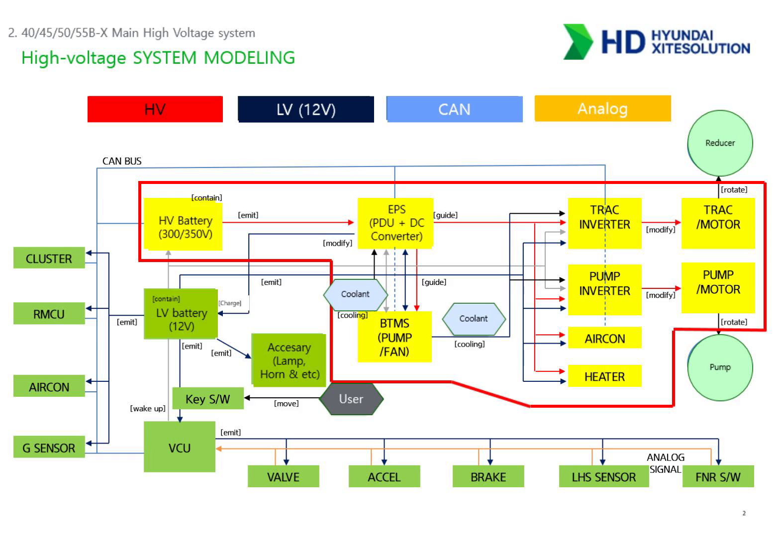
[Audio] Let's now look at how electrical power flows through this machine. The power system is divided into two levels — high voltage and low voltage. The HV battery, operating at 300 to 350 volts, is the main power source. It feeds into the EPS, which contains the PDU and DC Converter. The DC Converter steps down the high voltage to 12 volts, which charges the low-voltage battery and powers accessories like lights and the horn. From the EPS, high voltage is distributed to four destinations: the traction inverter for driving, the pump inverter for hydraulic work, the air conditioner, and the heater. The brain of the system is the VCU, or Vehicle Control Unit. It receives inputs from the accelerator, brake, valve lever, and the forward-neutral-reverse switch. It communicates with all controllers — inverters, BMS, cluster — through the CAN BUS network. When the operator turns the key on, it wakes up the VCU, which then initializes the high-voltage system. The BTMS, or Battery Thermal Management System, circulates coolant through the inverters and motors to manage heat. If thermal management fails, the system will automatically limit output to protect components. Always check the cooling pump and fan condition during service. For service work, keep these points in mind. Red lines in the diagram are high-voltage — always follow HV safety protocols. Black lines are 12-volt and can be treated like conventional electrical systems. If the machine fails to start or stops intermittently, check the CAN BUS wiring and termination resistors starting from the VCU. For traction or pump motor faults, check both the high-voltage input to the inverter and the control signal from the VCU. Analog signals from the pedals and levers come in through the orange lines directly to the VCU — check those first for sensor faults..
Scene 2 (2m 7s)
[Audio] This slide shows how high-voltage power is distributed from the battery to each major component. Everything starts with the HV battery. The charging inlet DC is where the external charger connects to charge the battery. The BTMS connects directly to the battery to manage its temperature and keep it performing optimally. High voltage from the battery flows into the central PDU, or Power Distribution Unit. The PDU acts as the main hub, distributing power to all driven components. Inside the PDU is an integrated DC-DC converter that steps high voltage down to 12 volts for conventional electrical devices throughout the machine. From the PDU, four major components receive high voltage. The traction motor and its inverter handle driving. The pump motor and its inverter handle hydraulic operations. The PTC heater provides cabin heating directly from high voltage. And the compressor pressurizes refrigerant for the air conditioning system. For service, here are the key points. All orange lines in this diagram are high-voltage lines. If any connector on the PDU, inverters, or heater is not fully seated or has a damaged seal, insulation faults will occur. When the entire machine loses power or a specific component like the heater or air conditioner stops working, check the PDU output terminals first rather than going directly to the battery. If charging speed drops suddenly or output is limited, use the diagnostic tool to check whether the BTMS cooling and heating functions are working correctly. If 12-volt systems like lights or the cluster are unstable, check the output of the DC-DC converter integrated inside the PDU..
Scene 3 (3m 52s)
[Audio] This slide shows the CAN communication network layout. Think of this as the map you use to decide which line to check first when the machine won't move or is showing error codes. The key distinction in practice is CAN 1 versus CAN 2. The machine uses two independent CAN channels, both running at 500 kilobits per second. CAN 1 connects all the critical components required for machine operation — the traction and pump inverters, PDU, HV battery, BTMS, VCU, and instrument cluster. If the machine fails to start at all, or cannot drive or work, check the CAN 1 line first. CAN 2 connects supplementary and optional devices — the HVAC air conditioning controller, compressor, RMCU remote management unit, and G-sensor. If the machine drives normally but the air conditioning doesn't work or the machine doesn't appear in the remote monitoring system, CAN 2 is where you look. Looking at the bottom of the diagram, you'll see that both the main and sub VCU connect to both CAN 1 and CAN 2. The VCU acts as a gateway, passing data between both networks. If an entire channel is showing communication errors, check the VCU connector and wiring for that specific port first. One more important point — when communication errors appear, don't assume the problem is always in the communication wiring itself. The blue solid lines going out from the central PDU are 12-volt power supply lines to each controller. Always verify that 12-volt power is properly reaching the affected controller before diving into the CAN bus wiring. For motor or battery communication errors, check CAN 1 lines and termination resistors. For HVAC or sensor communication errors, check CAN 2. And be careful when unplugging connectors during diagnosis — CAN communication is often daisy-chained, so removing one component's connector mid-line can cut communication to everything connected after it..
Scene 4 (6m 8s)
[Audio] This slide covers the detailed specifications of the major components. These are the numbers and manufacturer references your engineers will need for parts replacement and technical consultation in the field. Starting with the power source and charging system. The battery is made by Eneroc and has a nominal voltage of 307.2 volts. Capacity depends on the option selected — standard is 53 kilowatt-hours, option one is 70 kilowatt-hours, and option two is 93 kilowatt-hours. The charger is made by ADY Power and requires an input voltage of 380 volts AC plus or minus 10 percent. When assessing a customer site, check that the local power supply is stable within this range. Charger output comes in three types — 20 kilowatts, 40 kilowatts, and 120 kilowatts. For the drive system, both the traction and pump motors use Bosch Rexroth two-in-one units that integrate the motor and inverter into a single assembly. The traction motor is rated at 60 kilowatts continuous and 95 kilowatts peak, with an operating voltage range of 250 to 420 volts. The pump motor is rated at 33 kilowatts continuous and 45 kilowatts peak. Both motors are PMSM type, water-cooled, and rated IP67 for water and dust protection. Coolant management is directly tied to motor lifespan — treat it as a priority. The EPS unit is also from Bosch Rexroth and integrates the DC-DC converter at 12 volts, 2 kilowatts and the PDU into a single two-in-one unit. It includes a high-voltage interlock feature — if any high-voltage connector is accidentally disconnected, the system will automatically shut down for safety. The RC controller from Bosch Rexroth operates on 12 volts and manages input and output interfaces. The instrument cluster is made by Taeha and uses the same hardware as existing production models, but with newly developed software specific to high-voltage operation. For service: all core electrification parts — motors, inverters, EPS, and controller — are Bosch Rexroth products. The normal operating voltage range for motors and inverters is 250 to 420 volts — if battery voltage falls outside this range, errors will occur. Since both the EPS and motor system are water-cooled, any coolant leak or pump failure can cause thermal derating of high-voltage components. Always inspect coolant levels and pump condition regularly. And remember — even though these components are rated IP67, that rating only holds if all seals are correctly reinstalled after any service work..
Scene 5 (9m 12s)
[Audio] This slide covers the detailed specifications for the mechanical hardware and hydraulic components. Many of these parts are shared with or adapted from existing IC forklift models, so compatibility and serviceability are key topics here. Starting with the thermal management and steering system. The BTMS is made by BOA and has a cooling capacity of 5 to 8 kilowatts, with IP67 water protection. The steering unit is made by Danfoss, with a displacement of 125 cubic centimeters per revolution and a relief pressure of 120 bar. This is the same part used on the 40 and 50D-9VB engine model, so parts availability and service procedures are already familiar. For the hydraulic control and main pump: the MCV, or Main Control Valve, is made by Buchholz and is based on the MCV from the 4.5-ton LPG forklift, adapted for this model. It uses a Hall sensor for proportional motor control when the operator moves the lever — the same type as used on the 30B-X model. The main pump is made by Settima and uses an internal helical gear design, model GR47, with a displacement of 40 cubic centimeters per revolution. This pump type was specifically selected to reduce noise at low RPM idle conditions. For the brake and drive axle: the electromagnetic brake is made by Warner, model ERX200, and performs the electronic auto parking function. It runs on 12 volts and is rated IPX4 for water resistance. The drive axle is made by HDX and is the same unit shared with the D-9VB engine model, with a gear ratio of 11.692. The gearbox is made by Jinmyung Powertec — this is a newly designed reduction gearbox specific to electric models, with a gear ratio of 3.5. The steering axle is made by Anching and has been updated with new steering angles of 80.5 degrees and 58.4 degrees, improving the turning radius. Tires are made by Heung-A or Nexen and are the same spec as the D-9VB engine model. Single tires are 300-15 front and 7.00-12 rear. Dual tires are 7.50-16 front and 7.00-12 rear. For service: the steering unit, drive axle, and tires are all compatible with the existing 9VB engine model — use this for parts stock planning. If hydraulic operation is unstable or motor response is inconsistent, check the Hall sensor voltage signal at the MCV. The Settima pump was chosen for low noise — if you hear unusual high-frequency noise or vibration, inspect the pump gears and cooling system. If the machine is stuck in parking mode or the brake engages unexpectedly, check the 12-volt supply and connector condition at the Warner electromagnetic brake first..
Scene 6 (12m 23s)
[Audio] This slide shows the physical layout of high-voltage components inside the machine. The goal is to help your technicians quickly identify where each part is located when they open the covers during service work. Before we go through the layout, the most important point: any technician who has not completed high-voltage safety training must never perform maintenance or service on the high-voltage system. This is a mandatory HDX safety regulation, and non-compliance is life-threatening. Now let's look at where each component is located. Number one is the HV battery, located at the bottom center of the main frame — this is the primary power source. Number two is the BTMS, positioned behind the battery near the counterweight side, managing battery temperature. Number three is the traction motor, mounted near the front drive axle and responsible for driving. Number four is the pump motor, which handles hydraulic operation. Number five is the PDU, positioned near the top of the inverter assembly and easily accessible — this is where all high-voltage power is distributed from. Number six is the PTC heater for cabin heating, located at the lower front of the cab area. Number seven is the air conditioning compressor, mounted on the side of the battery area. And number eight is the HV cable — the orange-colored wiring connecting all these components. For service: any orange cable you see inside this machine is a high-voltage line. Even after disconnecting power, always measure voltage with a meter before touching any orange cable. When troubleshooting a power distribution issue, start by opening the PDU cover — number five — and checking the internal relays and fuses. This is the fastest diagnostic path. When inspecting the heater — number six — pay close attention to the insulation condition of the high-voltage wiring that enters the cabin area, as this is a sensitive zone..
Scene 7 (14m 33s)
[Audio] This slide covers the MSD — the Manual Service Disconnector. This is the first action any technician must take before beginning any high-voltage service work. Understanding this component is directly linked to personal safety. The MSD is a manual high-voltage cutoff device. Its purpose is to physically disconnect the high-voltage circuit during inspection, maintenance, or repair, protecting technicians from electrocution. The rule is simple and non-negotiable: no high-voltage service work begins without first removing the MSD. On this model, the MSD can be accessed from two locations. The primary access point is through the main bonnet — opening the central bonnet gives direct access to the MSD mounted on top of the battery. This is where the actual disconnection takes place. The secondary access point is through the side cover, which allows technicians to visually confirm the MSD location from the side of the machine. Here is the required three-step safety procedure your technicians must follow every time. Step one: disconnect the MSD. Open the bonnet, fully remove the MSD connector, and keep it on your person so no one else can reconnect it while you're working. Step two: wait for residual voltage to discharge. Removing the MSD does not instantly eliminate voltage — capacitors inside the system retain charge. Wait a minimum of five to ten minutes after removal before proceeding. Step three: measure voltage. Use a high-voltage rated multimeter on the input terminals of the component you're about to service, and confirm the reading is zero volts before touching anything. Two additional cautions: the MSD is a physical disconnect device, not a simple switch. Do not apply excessive force when removing it — learn the correct unlocking method to avoid damage. When reinstalling after work is complete, push it in fully until you hear a clear click. An incomplete connection will trigger an interlock error and the machine will not start..
Scene 8 (16m 43s)
[Audio] This slide covers the BTMS — the Battery Thermal Management System. This is an integrated water-cooled system that manages temperature across the high-voltage battery and all major drivetrain components. The BTMS monitors battery condition in real time and responds immediately to temperature changes. It is especially critical during fast charging and in high ambient temperature environments above 45 degrees Celsius, where battery temperature can rise rapidly without active cooling. By maintaining the battery at its optimal temperature range, the BTMS improves operating efficiency and extends overall battery lifespan. What makes this system notable is that it doesn't just cool the battery — it manages heat across all major components in a single integrated system. This includes the traction motor, pump motor, and their inverters. Looking at the diagram at the bottom of the slide, you can see how the coolant tank and piping connect to each component, circulating heat away from the entire system. For service, the key checks are as follows. Check coolant level and condition regularly — if coolant is low, battery temperature will rise and the system will force output reduction to protect itself. Inspect the large cooling fan shown in the photo on the right side of the slide. During heavy load operation or charging, confirm it is spinning correctly. Abnormal fan noise or a fan that's not running will trigger a BTMS fault. Use the diagnostic tool to monitor battery cell temperatures in real time and confirm the BTMS is responding within its target temperature range. When speaking with customers, you can explain it this way: even in outdoor environments where temperatures reach 45 degrees Celsius, this system actively cools the battery to keep operations stable. For sites that rely heavily on fast charging, BTMS performance is especially important — keep the area around the cooling pump and fan clear of debris..
Scene 9 (18m 45s)
[Audio] This slide shows the cooling line structure and how the thermal management system is organized into two separate circuits. The most important thing to understand here is that the battery cooling line and the machine body cooling line are physically separated from each other. Each circuit has its own pump, water tank, and piping — they do not share fluid or components. The battery cooling circuit is controlled by the BMS, which sends battery temperature data to the BTMS. This circuit uses a chiller for cooling. Because the battery is extremely sensitive to heat, the chiller provides more precise and powerful temperature control than a standard radiator, keeping the battery within its optimal operating range. The machine body cooling circuit is controlled by the VCU, which receives temperature data from the components it manages. This circuit cools the PDU, the traction inverter and motor, and the pump inverter and motor. It uses a conventional radiator for cooling — the same principle as a standard water-cooled engine. For service diagnosis, when an overheat alarm appears, immediately identify which circuit is affected. A battery overheat alarm means you check the chiller and the battery-dedicated cooling line. A motor or inverter overheat alarm means you check the radiator and the body component cooling line. Never mix the two circuits during maintenance or fluid top-up. They are independent systems and must be serviced separately..
Scene 10 (20m 19s)
[Audio] This slide gives a closer look at the detailed hardware structure of the BTMS and how the two cooling lines are physically laid out. As covered in the previous slide, the battery cooling line and the body component cooling line are completely independent. Each has its own pump, water tank, and piping installed separately, with no shared components between them. The cooling method differs between the two circuits. The battery line uses a chiller, which cools the coolant through indirect cooling — meaning the coolant is cooled by a refrigerant loop rather than direct air contact. This allows for more precise temperature control. The body component line uses a radiator fan for direct air cooling, which is the conventional method used in most water-cooled systems. An important distinction for service work is the operating voltage of each component inside the BTMS. The pump and fan run on 12 volts — standard low-voltage components. However, the compressor runs on high voltage directly. Always treat the compressor as a high-voltage component and follow full HV safety procedures when servicing it. When checking the physical connections, the ports at the top are the coolant inlet and outlet for the battery circuit. The ports at the bottom are the coolant inlet and outlet for the motor circuit. Regularly inspect the HV power connector, the LV power and signal connectors, and the coolant level sensor to confirm they are all securely seated and undamaged..
Scene 11 (21m 52s)
[Audio] This slide explains the PMSM — the Permanent Magnet Synchronous Motor — and why it was chosen for this machine over a conventional induction motor. PMSM stands for Permanent Magnet Synchronous Motor. The rotor uses powerful neodymium permanent magnets, which allows for higher efficiency and more precise control compared to standard induction motors. On this machine, PMSM is used for both the traction motor and the hydraulic pump motor. Let's compare the two types directly. An induction motor, or IM, uses conductors and iron cores in the rotor. It operates with what is called slip — meaning the rotor always runs slightly slower than the magnetic field. Efficiency typically falls in the 85 to 90 percent range, control precision is average, and response speed is slow. The PMSM, by contrast, uses permanent magnets. It operates in perfect synchronization with the magnetic field — no slip. Efficiency is 90 to 95 percent, control precision is excellent, and response is fast. For high-voltage safety: the motor is connected to the high-voltage system. Never open the motor cover until the MSD has been disconnected and voltage has been confirmed at zero volts. For service guidelines: technicians in the field should perform insulation resistance measurement, connector seating checks, and cooling line inspection. If internal motor noise is detected or insulation breakdown is confirmed, do not attempt to disassemble the motor. Replace it as a complete assembly or send the unit to the main service center. Make sure your team understands this clearly — field disassembly of the motor is not the correct procedure..
Scene 12 (23m 41s)
[Audio] This slide compares the different types of motors that were evaluated during development, so you can explain clearly why the neodymium PMSM was selected for this machine. Looking at efficiency first: among all the motor types evaluated, the neodymium permanent magnet motor — Nd-PM — achieves the highest efficiency. The ranking from lowest to highest goes: induction motor, then SynRM, then ferrite permanent magnet, and finally the Nd-PM at the top. For price, the Nd-PM is the most expensive option — approximately 150 percent of the cost of a standard induction motor. This is because it uses neodymium, a rare earth material with a very strong magnetic field. For size and weight, the Nd-PM is the smallest among the options evaluated. A more compact and lighter motor that still delivers strong output means better space utilization inside the machine and improved energy efficiency. For noise and vibration, all motor types perform at a comparable and acceptable level with proper design. One exception is the SynRM, which has inherently higher torque ripple, making it more prone to noise and vibration issues. The Nd-PM in this machine does not have this problem and maintains stable operation. One key risk worth mentioning: every motor type has a limitation. For the Nd-PM used in this machine, the risk is rare earth material supply — neodymium sourcing is sensitive to global supply chain conditions. This is a known industry challenge and something to be aware of when discussing long-term parts availability with customers..
Scene 13 (25m 26s)
[Audio] This final slide provides a more detailed comparison of motor types, with the neodymium PMSM highlighted in yellow as the motor used in our machine. The neodymium PMSM is the same motor technology used in passenger electric vehicles. It offers the highest power density of all motor types reviewed — meaning it delivers excellent efficiency in a very compact package. The motor size is approximately 55 percent of an equivalent induction motor, which significantly reduces weight and frees up space in the machine design. One technical challenge during development was the risk of irreversible demagnetization — this is a condition where the permanent magnets can lose their magnetic strength permanently if the motor operates at very high temperatures. This risk was addressed through detailed thermodynamic analysis and extensive testing, and the issue has been resolved in the final design. In terms of cost, the neodymium PMSM is priced at approximately 150 percent of a standard induction motor — the most expensive option in the comparison. However, when you factor in the efficiency gains, the reduction in motor size and weight, and the performance advantages for heavy-duty industrial use, this technology represents the right choice for this application..